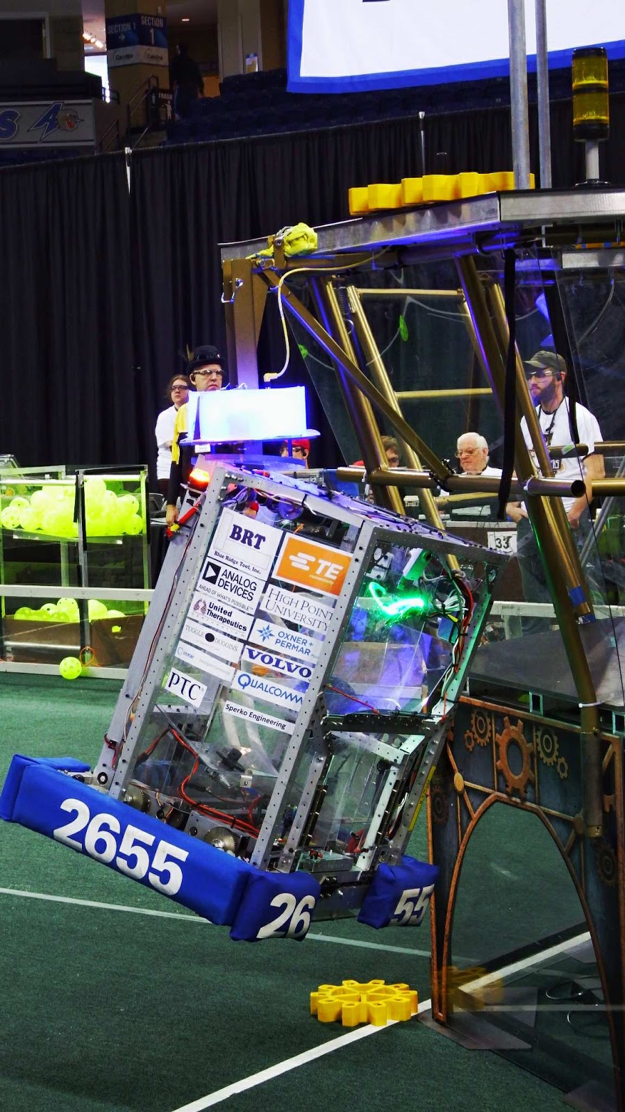
This is the documentation for FIRST Robotics Competition Team #2655 – The Flying Platypi’s 2017 competition robot, Unhinged. The code is written in LabVIEW and contains many features, most notably:
- An Autonomous Scripting system to allow us to easily write and customize Autonomous routines for any situation.
- The option to use either an IMU or a Teensy Gyro.
- We wrote adaptable vision code to detect and compare vision targets, calculate the angle of deviation between them, and calculate the distance between the robot and the target.
- Use of CAN Talon SRXs to control the drive motors and the shooter motor using speed mode
Autonomous Scripting
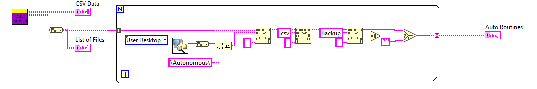
For creating Autonomous routines we made a system to make it easy enough for anyone to create a routine. Our Script Crafter (https://github.com/MB3hel/Java-Team2655AutonomousScriptCrafter) allows drivers to create autonomous scripts on the driver station through a user friendly GUI. This script can be read in the Dashboard code using the Array Parser .vi and the CSV Parsing .vi. CSV Parsing is used to read all of the information from the .csv file and the Array Parser is used to convert this information to an array that can be used as a routine. This array is then sent to from the dashboard the robot code using the Array to Autonomous Commands.vi. The robot code then converts this to functions to run.
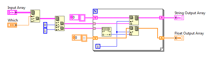
 Array Parser.vi
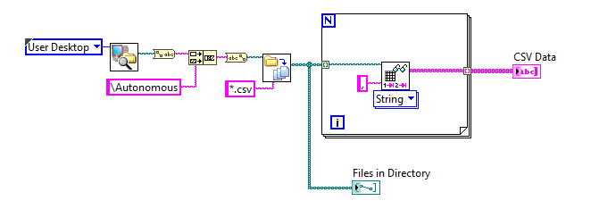
CSV Parser.vi
Array to Autonomous Commands.vi
Autonomous Functions
For each function of the robot, there is a function that is selected in the code using the case structure. Each of these cases has an input, known as the argument, that is used wherever it is needed within the case.
DRIVE_FAST
This case is used to drive forward at 80% speed until it reaches the length specified by the argument, which should be measured in inches.
DRIVE_SLOW
This case is used to drive forward at 50% speed until it reaches the length specified by the argument, which should be measured in inches.
STRAFE
This case is used to strafe at full speed until it reaches the length specified by the argument, which should be measured in inches. It has a PID loop on the rotation, so it should strafe in a straight line. Negative arguments will make the robot strafe left and positive arguments will make it strafe right.
STOP
This case stops all four drive motors, the ball intake motor, the agitator motor, and the shooter motor. There is no argument required for this function. This should only be and always be used at the end of a routine.
RESET_GYRO
This executes the 16448 reset function within the Teensy code. This has no argument and should be used at the beginning of an Autonomous routine. This function could take time, so it should not be used if your routine is already close to 15 seconds.
WAIT
This function is used to make the robot wait a specified number of seconds, which is determined by the argument.
ROTATE
This case uses a PID loop to rotate the robot. The argument, measured in degrees, will set the distance that the robot will turn. It will run until the Z angle of the IMU is within half a degree of the argument. It will timeout after two seconds.
VISION_ALIGN_ROTATE
This function automatically aligns the robot to within 2 degrees of the gear lifter using the USB camera. It requires no argument.
SHOOT_HIGH
This runs the shooter and the agitator.Takes the initial time and will continuously shoot until the argument,measured in seconds, has been reached.
OPEN_GATE
This opens the servos on the gear holder to drop a gear at one of the gear pegs.
CLOSE_GATE
This closes the servos on the gear holder to hold a gear.
Vision Code
Vision Angle
The VisionAngle.vi uses the view angle of the camera and the position of the target in the image to determine the angle the robot needs to rotate to face the vision target. We can then use this information and the gyro to align properly.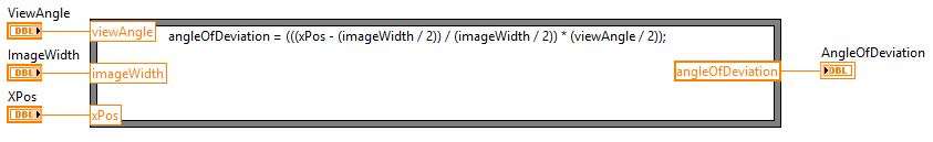
Gear Vision Tracking
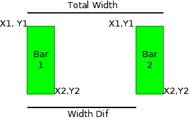
In order to track the vision target around the gear pegs, we adapted the FRC vision example to work for a different target. We modified the default Cull and Group.vi, Compute Distance To Target.vi, and the Rectangle Comparison.vi. The Rectangle Compare.vi compares each rectangle in the target against the other and, if they are the right sizes and ratios, they are accepted as a target. The math done in the Rectangle Compare.vi was adapted to compare the rectangles for the gears. The math is done in C for simplicity and is made to be easily adapted to other targets. The formula node (containing the C code) outputs an array of 5 floats that make up the score and an array of line points for a line that crosses through the centers of the targets. We also added a margin for the line and the bounding box for tuning purposes. The outputted array contains five numbers (percent in decimal form) for the following
- Relative Width of the Left bar
- Relative Distance between the bars
- Relative Distance between the tops of the bars
- Width Ratio (bar1 to bar2)
- Height Ratio (bar1 to bar2)
Relative measurements are relative to the total width (or height) (left of bar 1 to right of bar 2) of the target.